John and Heather Innis
Home · Toys · Projects · Arduino · WiiChuckCarLow Cost Automotive Performance Meter
using a Wii Nunchuck and an Arduino
The goal of this project was to give me
a simple and inexpensive way to tell if the changes I was making to my
car were making the performance better or worse. I
got this idea from a couple of different sources. First was a
project from Make Magazine's
Podcast that involved a Wii Nunchuck accelerometer and an Arduino to
capture and display acceleration. The second was an automotive
application on HackWii
using a WiiMote and a laptop to measure the acceleration of a
car. I had an Arduino and a Wii, so I decided to try and combine
these.
The idea is simple. Starting from rest, if I measure the acceleration of the car, and take a time stamp, I can figure out how fast the car is moving. No fancy math is required, just using a=vf-v0*(tf-t0), where a = acceleration (in m/s/s) vf = the final velocity, or the speed of the car at the end of a period of time (tf) and v0 = the initial velocity or the speed of the car at the start of the period of time (t0).
I had a Wii Nunchuck from my game system and an Arduino with a datalogging shield that I have used for other projects in the past. I bought a WiiChuck adapter from SparkFun so that I could use the Nunchuck for this project without modifying it. I bought a prototype shield and an LCD from adafruit. I didn't really need the prototype shield, but with this and some stacking headers for all my shields I can make my Arduino projects more modular, and expandable. The Wires in the photo below are also from adafruit, they come as six pin straight through connections, but the pins are easy to remove from the plastic shells. I rearranged the wires to match of the pinout of the LCD to the pins I needed on the Arduino.
I got the nunchuck_funcs.h library from todbot.com. There were a few issues with this library and the way it handled the 10 bit accelerometer data being split over two words in the I2C data, so I updated it and stripped out all the stuff I didn't need (mostly print functions). I combined the example sketch from todbot.com with some LCD stuff from the Arduino examples, and had a working version pretty quick.
First I needed to figure out what the Wii Nunchuck was sending me and how it related to something in si units. The Nunchuck does NOT measure in g's or m/s/s or any other specific unit, it's reading are all relative. The data is a 10-bit unsigned integer. I used a flat level surface to map out the accelerometer reading I got from the WiiChuck when it was at different positions. I am using the convention that was already present in the nunchuck_funcs.h for axis naming, where the x axis is side-to-side motion, the y-axis is forward/backward motion, and the z-axis is up and down motion. I wrote the first part of my Arduino sketch to just dump the raw accelerometer data to the LCD and the Serial Port.
I found that with the Nunchuck in the normal upright position, I get 508 in the x-axis, 512 in the y-axis, and 808 in the z-axis. This means that these are the null or 0g points for x and y and the 1g point for the z axis. Rotating the wii chuck, I found the null, 1g and -1g points for x,y, and z as follows.
Based on these and some additional static position readings, I was able to work out a linear scale of the force reading from the accelerometer for each axis. I found that for my Nunchuck the following formulas will gave me acceleration in g's and m/s/s:
(accel - null) / scale = accel_g
((accel - null) / scale)*9.8067 = accel_mss
Where accel is the raw data from the Nunchuck, null is the null point from the table above, and scale is as follows for each axis:
Note that these values seem to vary a bit from one nunchuck to the next, so the null and scale values will have to be figured out for each individual unit.
Now that I could translate the data from the accelerometer, I needed to use that to figure out how fast the car was moving. I set up me acceleration run sketch to start with the car stationary so that I would know that v0 is 0. Without this, there is no way to determine how fast we are moving. The sketch takes a timestamp with millis, then starts reading the accelerometer data in a loop. Each time it compares the time stamp to the one from the previous iteration and uses the current acceleration to figure out how fast the car is moving.
speed = speed + ( acceleration * time )
Or more precisely:
speed_present = speed_previous + (acceleration * (time_present - time_previous))
And since I know know speed and time I can also find distance (from the point that the car started moving) as:
distance_presnet = distance_previous + (speed * (time_present - time_previous))
With acceleration, speed and distance, I now have all the data I need to measure the performance of the car in the most familiar terms, force, 0-60 time, and 1/4 mile time. I simply watch for speed to reach 26.82 m/s (60 mph) and display this on the LCD as 0-60 time. Then watch for distance to reach 402.3m (1/4 mile) and show the 1/4 mile elapsed time. I coded all this up in my sketch and had a working display system in short order.
Next I added in some datalogging functions derived from the sample sketch that adafruit.com provide with their datalogging sheild. After adding this in, the sketch would compile, but kept crashing during runtime. I tracked the problem to the way I was doing my LCD stuff. I tried to get fancy by concatenating strings and passing them to a draw function, which worked fine until I added in the code and headers for writing to the SD card on the datalogging shield. I think I was runnning out of RAM or had some sort of memory contention, so I just went to a simple element by element LCD approach, and everything was working again.
Here is the completed sketch code along with my modified nunchuck_funcs.h library: WiiChuckCar.zip
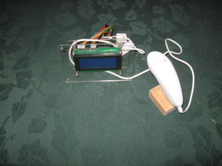
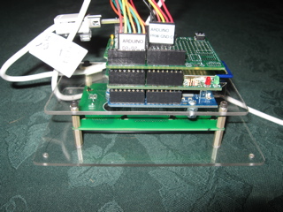
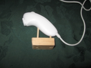
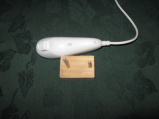
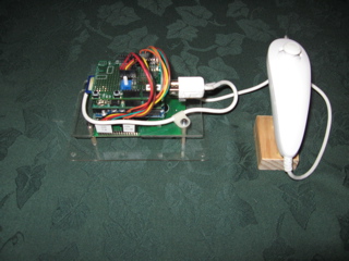
I mounted the LCD to a peice of Plexiglas with some standoff's and then the Arduino to another peice of plexi behind that. The datalogging shield and the proto shiled LCD interface were stacked to the Arduino. I also built a small stand to mount the Wii Nunchuck to that was solid but easily removable. A couple dowel rods sanded down fint nice and snug into the assembly screw holes on the Nunchuck. Once mounted in a small block of wood I have a nice stable platform that is easily removeable. I intended to put this basic stand on a gimbal with adjustors so I could level the wii chuck in the car and limit the longitudanal acceleration of the car to the Y-Axis of the Nunchuck accleerometer. I shoud have known at this point that I was going to have an issue.
In the real world this project works great .... as long as the road is straight and level. But as soon as the road rises or falls, the angle of the longitudanal acceleration of the car with respect to acceleration of garvity means I can not tell if the acceleration I am reading is the car's velocity changing or if it's pitch angle is changing. I have not yet figured out how to get the system to tell the difference between a change in grade of the road and a change in the speed of the car. If I am acclerating along a straight level road, speed and distance are accurate. But if I start going up a hill, the accelerometer thinks I am slowing down. Because the equations always depend on konwing the speed from the previous iteration, even a slight grad for a short time makes all the speed and distance data useless. I think I would need another sensor, perhaps a rotational accleration sensor that is insensitive to gravity. But that would likely drive the cost of the project beyoned the limits of my hobby budget, so for now that remains a future improvement.
Unfortunatly level roads are few and far between in this part of the world, and those that exist are not appropiate for this sport of testing, so accurate 0-60 and 1/4 mile times are not possible with this set up. But, more importantly, I can get the accleration data from each run logged for future refernece. So, if I always use the same peice of road, I can tell if a given run is better or worse than previous runs.
The idea is simple. Starting from rest, if I measure the acceleration of the car, and take a time stamp, I can figure out how fast the car is moving. No fancy math is required, just using a=vf-v0*(tf-t0), where a = acceleration (in m/s/s) vf = the final velocity, or the speed of the car at the end of a period of time (tf) and v0 = the initial velocity or the speed of the car at the start of the period of time (t0).
I had a Wii Nunchuck from my game system and an Arduino with a datalogging shield that I have used for other projects in the past. I bought a WiiChuck adapter from SparkFun so that I could use the Nunchuck for this project without modifying it. I bought a prototype shield and an LCD from adafruit. I didn't really need the prototype shield, but with this and some stacking headers for all my shields I can make my Arduino projects more modular, and expandable. The Wires in the photo below are also from adafruit, they come as six pin straight through connections, but the pins are easy to remove from the plastic shells. I rearranged the wires to match of the pinout of the LCD to the pins I needed on the Arduino.
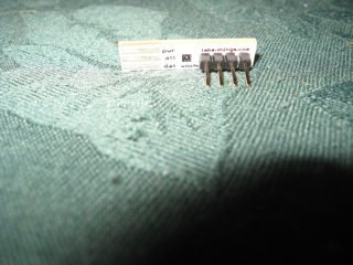 WiiChuck Adapter |
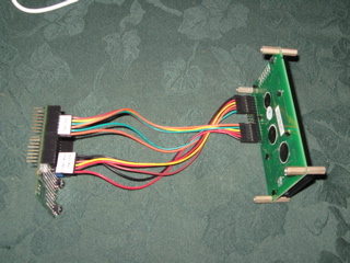 Assembled LCD and Prototype Shield |
I got the nunchuck_funcs.h library from todbot.com. There were a few issues with this library and the way it handled the 10 bit accelerometer data being split over two words in the I2C data, so I updated it and stripped out all the stuff I didn't need (mostly print functions). I combined the example sketch from todbot.com with some LCD stuff from the Arduino examples, and had a working version pretty quick.
First I needed to figure out what the Wii Nunchuck was sending me and how it related to something in si units. The Nunchuck does NOT measure in g's or m/s/s or any other specific unit, it's reading are all relative. The data is a 10-bit unsigned integer. I used a flat level surface to map out the accelerometer reading I got from the WiiChuck when it was at different positions. I am using the convention that was already present in the nunchuck_funcs.h for axis naming, where the x axis is side-to-side motion, the y-axis is forward/backward motion, and the z-axis is up and down motion. I wrote the first part of my Arduino sketch to just dump the raw accelerometer data to the LCD and the Serial Port.
I found that with the Nunchuck in the normal upright position, I get 508 in the x-axis, 512 in the y-axis, and 808 in the z-axis. This means that these are the null or 0g points for x and y and the 1g point for the z axis. Rotating the wii chuck, I found the null, 1g and -1g points for x,y, and z as follows.
| -1g |
0g |
+1g |
|
| X |
296 |
508 |
718 |
| Y |
291 |
512 |
722 |
| Z |
372 |
602 |
808 |
Based on these and some additional static position readings, I was able to work out a linear scale of the force reading from the accelerometer for each axis. I found that for my Nunchuck the following formulas will gave me acceleration in g's and m/s/s:
(accel - null) / scale = accel_g
((accel - null) / scale)*9.8067 = accel_mss
Where accel is the raw data from the Nunchuck, null is the null point from the table above, and scale is as follows for each axis:
| scale |
|
| X |
211 |
| Y |
215.5 |
| Z |
218 |
Note that these values seem to vary a bit from one nunchuck to the next, so the null and scale values will have to be figured out for each individual unit.
Now that I could translate the data from the accelerometer, I needed to use that to figure out how fast the car was moving. I set up me acceleration run sketch to start with the car stationary so that I would know that v0 is 0. Without this, there is no way to determine how fast we are moving. The sketch takes a timestamp with millis, then starts reading the accelerometer data in a loop. Each time it compares the time stamp to the one from the previous iteration and uses the current acceleration to figure out how fast the car is moving.
speed = speed + ( acceleration * time )
Or more precisely:
speed_present = speed_previous + (acceleration * (time_present - time_previous))
And since I know know speed and time I can also find distance (from the point that the car started moving) as:
distance_presnet = distance_previous + (speed * (time_present - time_previous))
With acceleration, speed and distance, I now have all the data I need to measure the performance of the car in the most familiar terms, force, 0-60 time, and 1/4 mile time. I simply watch for speed to reach 26.82 m/s (60 mph) and display this on the LCD as 0-60 time. Then watch for distance to reach 402.3m (1/4 mile) and show the 1/4 mile elapsed time. I coded all this up in my sketch and had a working display system in short order.
Next I added in some datalogging functions derived from the sample sketch that adafruit.com provide with their datalogging sheild. After adding this in, the sketch would compile, but kept crashing during runtime. I tracked the problem to the way I was doing my LCD stuff. I tried to get fancy by concatenating strings and passing them to a draw function, which worked fine until I added in the code and headers for writing to the SD card on the datalogging shield. I think I was runnning out of RAM or had some sort of memory contention, so I just went to a simple element by element LCD approach, and everything was working again.
Here is the completed sketch code along with my modified nunchuck_funcs.h library: WiiChuckCar.zip
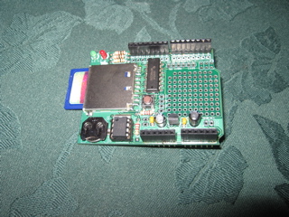 adafruit dataloging shield |
 Assemebeled Project |
I mounted the LCD to a peice of Plexiglas with some standoff's and then the Arduino to another peice of plexi behind that. The datalogging shield and the proto shiled LCD interface were stacked to the Arduino. I also built a small stand to mount the Wii Nunchuck to that was solid but easily removable. A couple dowel rods sanded down fint nice and snug into the assembly screw holes on the Nunchuck. Once mounted in a small block of wood I have a nice stable platform that is easily removeable. I intended to put this basic stand on a gimbal with adjustors so I could level the wii chuck in the car and limit the longitudanal acceleration of the car to the Y-Axis of the Nunchuck accleerometer. I shoud have known at this point that I was going to have an issue.
 Nunchuck on Stand |
 Nunchuck and Stand |
 Finsihed project, rear view |
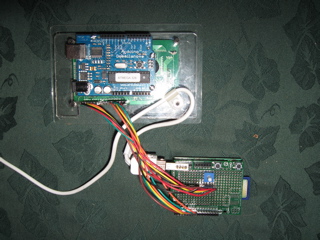 Shields Removed, showing Arduino and mount |
In the real world this project works great .... as long as the road is straight and level. But as soon as the road rises or falls, the angle of the longitudanal acceleration of the car with respect to acceleration of garvity means I can not tell if the acceleration I am reading is the car's velocity changing or if it's pitch angle is changing. I have not yet figured out how to get the system to tell the difference between a change in grade of the road and a change in the speed of the car. If I am acclerating along a straight level road, speed and distance are accurate. But if I start going up a hill, the accelerometer thinks I am slowing down. Because the equations always depend on konwing the speed from the previous iteration, even a slight grad for a short time makes all the speed and distance data useless. I think I would need another sensor, perhaps a rotational accleration sensor that is insensitive to gravity. But that would likely drive the cost of the project beyoned the limits of my hobby budget, so for now that remains a future improvement.
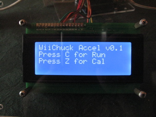 Finished project menu screen |
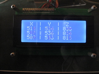 Finished Calibration mode, showing live accelerometer data |
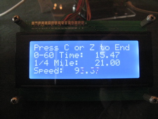 Finished project acceleration mode screen |
Unfortunatly level roads are few and far between in this part of the world, and those that exist are not appropiate for this sport of testing, so accurate 0-60 and 1/4 mile times are not possible with this set up. But, more importantly, I can get the accleration data from each run logged for future refernece. So, if I always use the same peice of road, I can tell if a given run is better or worse than previous runs.
Return to our Home Page or back up to Arduino
Mac and the Mac logo are trademarks of Apple Computer, Inc., registered in the U.S. and other countries. The Made on a Mac Badge is a trademark of Apple Computer, Inc., used with permission.

This web site and all content is © 2005 - 2011 John D Innis
Email me Here!
